
- COMPOSITE VIDEO TO VGA CONVERTER SCHEMATIC GENERATOR
- COMPOSITE VIDEO TO VGA CONVERTER SCHEMATIC CODE
- COMPOSITE VIDEO TO VGA CONVERTER SCHEMATIC TV
To use are 0x00/0xAA when intensity is low, and 0x55/0xFF when high. Same thing for green and blue).įirst of all, there is a spcial exception for yellow (to get a nice brown instead of a sickly dark yellow). (Example: For the red output, if the intensity bit is high, output will be 0xff or 0x7f depending on the CGA red bit, and if intensity is 0, the output will be either 0x00 or 0x7f. A composite-to-VGA converter is more complicated to design, especially considering that the signal isnt exactly according to the standard. Instead it keeps an internal copy of the graphics memory, and generates the VGA signal from that.
COMPOSITE VIDEO TO VGA CONVERTER SCHEMATIC CODE
I had initially written code that did the RGBI to RGB conversion using a simple It does not use the video generator/signal, so there is no distinction between NTSC/PAL systems. One of the final touch was implementing correct colors. Still see a bit of jitter, but it is within what I consider quite acceptable. Resisted and persevered to finally obtain a stable picture! The pixel clock (through a BNC connector I would add at the back) but I I was tempted more than once to modify my Tandy 1000 computer to extract Such as dancing lines, deformed characters. Otherwise, there are interesting but undesirable special effects Is to keep the time between pixel sampling and the hsync pulse constant (prevents It by resetting the division counters to zero after each CGA hsync.
COMPOSITE VIDEO TO VGA CONVERTER SCHEMATIC TV
The high frequency clock (they are therefore in phase). schematics, jual converter vga to hdmi tokopedia, tehnik service vga to video composite converter, simple vga to av converter circuit diagram wordpress com, vga to tv converter audio video circuits, cn0282 circuit note analog devices, av to vga converter schematics edaboard com, cga to vga converter circuit diagram looking for diy circuit. So I a lower frequency clock derived by dividing But I can't use the same highįrequency to store scanline data since the required buffer becomes too large VGA converter for video projectors and fixed frequency monitors S chematics wiring diagram circuits schema electronic projects. To properly synchronise tothe HSYNC edge. VEK4601 - Audio / Video Transmitter Kit S chematics wiring diagram circuits schema electronic projects.
COMPOSITE VIDEO TO VGA CONVERTER SCHEMATIC GENERATOR
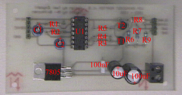
Generator clock (the pixel clock) I have to sample at a much higher frequency I want to drive all the signals together, i.e. The circuit is quite simple, because RGB signal ouput from VGA card is already standard 0.7Vpp to 75 ohm load. This circuit is designed for converting normal VGA signals standard RGB signals and composite sync signal. Please ignore the H-SYNC and V-Sync inputs I will fix it to do C-Sync. This circuit has been succesfully used with Electrohome Projection Systems ECP 4100 data and video projector.

Thread starter aarkay14 Start date aarkay14. First, as I don't have access to the CGA video Analog RGBS to S-Video and Composite Video converter schematic verify request. Too much jitter There were many difficulties.


 0 kommentar(er)
